We’ll start by learning a little about how MQTT, Tasmota and Home Assistant work together.
Using the https://mqttx.app/ CLI
We have a Tasmota device set up interacting via the MQTT broker integrated with Home Assistant, Mosquitto. The Tasmota device is a smart plug from Local Bytes.
Let’s see what messages are flowing through it, using the CLI.
Assume the MQTT username and password are set as
$MQTT_USER and $MQTT_PASSWORD.
mqttx sub -t '#' -h homeassistant.lan -p 1883 -u $MQTT_USER -P $MQTT_PASSWORDsub - subscribe-t - to the topic# - wildcard meaning all topics-h - host or ip address on which the broker is
runninghomeassistant.lan - if your router provides this, else
you’ll need to use the Home Assistant IP address-p - port for the broker, 1883 is the
standard-u and -P - username and passwordResult
✔ Connected
✔ Subscribed to #
topic: tele/tasmota_DEVICE_SHORT_ID/LWT, qos: 0, retain: true
Online

topic: tasmota/discovery/DEVICE_ID/config, qos: 0, retain: true
{"ip":"10.10.10.119","dn":"DEVICE_NAME","fn":["DEVICE_NAME",null,null,null,null,null,null,null],"hn":"tasmota-DEVICE_SHORT_ID-7525","mac":"DEVICE_ID","md":"LocalBytes PM","ty":0,"if":0,"ofln":"Offline","onln":"Online","state":["OFF","ON","TOGGLE","HOLD"],"sw":"12.2.0","t":"tasmota_DEVICE_SHORT_ID","ft":"%prefix%/%topic%/","tp":["cmnd","stat","tele"],"rl":[1,0,0,0,0,0,0,0],"swc":[-1,-1,-1,-1,-1,-1,-1,-1],"swn":[null,null,null,null,null,null,null,null],"btn":[0,0,0,0,0,0,0,0],"so":{"4":0,"11":0,"13":0,"17":0,"20":0,"30":0,"68":0,"73":0,"82":0,"114":0,"117":0},"lk":0,"lt_st":0,"sho":[0,0,0,0],"sht":[[0,0,0],[0,0,0],[0,0,0],[0,0,0]],"ver":1}

topic: tasmota/discovery/DEVICE_ID/sensors, qos: 0, retain: true
{"sn":{"Time":"2025-06-24T09:24:12","ENERGY":{"TotalStartTime":"2025-04-27T15:09:47","Total":0.513,"Yesterday":0.007,"Today":0.000,"Power":0,
 "ApparentPower":0,"ReactivePower":0,"Factor":0.00,"Voltage":0,"Current":0.000}},"ver":1}
As soon as we connect, we see some messages on the bus, across
various topics. We see all three have retain: true flag
set. It seems that a topic will publish
the last retained message to any future subscribers.
The latter two messages are published in topics with discovery in the path, suggesting these are used for autodiscovery of Tasmota devices by the Tasmota integration in Home Assistant.
Continuing to listen for MQTT messages, we’ll see some more telemetry/logging messages coming from the Tasmota device, e.g.
topic: tele/tasmota_DEVICE_SHORT_ID/STATE, qos: 0
{"Time":"2025-06-24T14:47:14","Uptime":"42T18:36:53","UptimeSec":3695813,"Heap":26,"SleepMode":"Dynamic","Sleep":50,"LoadAvg":19,"MqttCount":123,"POWER":"OFF","Wifi":{"AP":1,"SSId":"SSID","BSSId":"BSSID","Channel":6,"Mode":"11n","RSSI":58,"Signal":-71,"LinkCount":1,"Downtime":"0T00:00:03"}}

topic: tele/tasmota_DEVICE_SHORT_ID/SENSOR, qos: 0
{"Time":"2025-06-24T14:47:14","ENERGY":{"TotalStartTime":"2025-04-27T15:09:47","Total":0.513,"Yesterday":0.007,"Today":0.000,"Period":0,"Power":0,"ApparentPower":0,"ReactivePower":0,"Factor":0.00,"Voltage":0,"Current":0.000}}

topic: stat/tasmota_DEVICE_SHORT_ID/LOGGING, qos: 0
14:47:14.497 MQT: tele/tasmota_DEVICE_SHORT_ID/STATE = {"Time":"2025-06-24T14:47:14","Uptime":"42T18:36:53","UptimeSec":3695813,"Heap":26,"SleepMode":"Dynamic","Sleep":50,"LoadAvg":19,"MqttCount":123,"POWER":"OFF","Wifi":{"AP":1,"SSId":"SSID","BSSId":"BSSID","Channel":6,"Mode":"11n","RSSI":58,"Signal":-71,"LinkCount":1,"Downtime":"0T00:00:03"}}
The content of these messages is not too important for us - it’s clear that key device/diagnostic information like power on/off, total power consumption, WiFi connection, etc… are being reported in these message, and that the messages meant for consumption by the Home Assistant system (i.e. not the logging messages) are all in JSON format. We see from the logging messages that this is not mandatory - the content can be at least any ASCII string.
mqttx allows us to publish messages.
mqttx pub -t 'test/topic/1' -m 'test content' -h homeassistant.lan -p 1883 -u $MQTT_USER -P $MQTT_PASSWORD
✔ Connected
✔ Message published
Instantly in the terminal where we are listening on all topics, we will see
topic: test/topic/1, qos: 0
test content
It’s that easy!
Suppose we now toggle the Tasmota device via Home Assistant. We should be able to see how Tasmota effects that change via MQTT.
We see these five messages in the listener terminal
topic: cmnd/tasmota_DEVICE_SHORT_ID/Power1, qos: 0
ON

topic: stat/tasmota_DEVICE_SHORT_ID/RESULT, qos: 0
{"POWER":"ON"}

topic: stat/tasmota_DEVICE_SHORT_ID/POWER, qos: 0
ON

topic: stat/tasmota_DEVICE_SHORT_ID/LOGGING, qos: 0
14:58:21.424 MQT: stat/tasmota_DEVICE_SHORT_ID/RESULT = {"POWER":"ON"}

topic: stat/tasmota_DEVICE_SHORT_ID/LOGGING, qos: 0
14:58:21.427 MQT: stat/tasmota_DEVICE_SHORT_ID/POWER = ON
The latter two are logging messages, I think not used operationally
by Home Assistant. From the prefix cmnd (I guess “command”)
I would imagine Home Assistant publishes messages on that topic to
control the device, and from the prefix stat (I guess
“status”) I would imagine the Tasmota device reports back its status to
Home Assistant. The logging messages back up these assertions - it seems
that the Tasmota device only publishes logs of the messages it sends,
not those it receives.
Switching off, basically the same, except OFF replaces
ON.
topic: cmnd/tasmota_DEVICE_SHORT_ID/Power1, qos: 0
OFF

topic: stat/tasmota_DEVICE_SHORT_ID/RESULT, qos: 0
{"POWER":"OFF"}

topic: stat/tasmota_DEVICE_SHORT_ID/POWER, qos: 0
OFF

topic: stat/tasmota_DEVICE_SHORT_ID/LOGGING, qos: 0
14:58:44.757 MQT: stat/tasmota_DEVICE_SHORT_ID/RESULT = {"POWER":"OFF"}

topic: stat/tasmota_DEVICE_SHORT_ID/LOGGING, qos: 0
14:58:44.760 MQT: stat/tasmota_DEVICE_SHORT_ID/POWER = OFFCan we use this dangerous knowledge to control our Tasmota device from the command line? If the understand we have built above is correct, then it should be easy.
mqttx pub -t 'cmnd/tasmota_DEVICE_SHORT_ID/Power1' -m 'ON' -h homeassistant.lan -p 1883 -u $MQTT_USER -P $MQTT_PASSWORDAs soon as the message is published, the switch turns ON and we see in the listener terminal window
topic: cmnd/tasmota_DEVICE_SHORT_ID/Power1, qos: 0
ON

topic: stat/tasmota_DEVICE_SHORT_ID/RESULT, qos: 0
{"POWER":"ON"}

topic: stat/tasmota_DEVICE_SHORT_ID/POWER, qos: 0
ON

...
Additionally, we see the state of the switch in Home Assistant as on, so it’s all self-consistent.
Switching the device off
mqttx pub -t 'cmnd/tasmota_DEVICE_SHORT_ID/Power1' -m 'OFF' -h homeassistant.lan -p 1883 -u $MQTT_USER -P $MQTT_PASSWORDhas all the expected opposite effects - switch turns off, OFF messages captured by the listener, state is off in Home Assistant.
Now we know how the Tasmota device reports back its state to Home Assistant, can we trick Home Assistant into thinking the switch is in the opposite state?
mqttx pub -t 'stat/tasmota_DEVICE_SHORT_ID/RESULT' -m '{"POWER":"OFF"}' -h homeassistant.lan -p 1883 -u $MQTT_USER -P $MQTT_PASSWORDPublishing this messages causes the state in Home Assistant to toggle to on, even though the switch is not on!
mqttx pub -t 'stat/tasmota_DEVICE_SHORT_ID/POWER' -m 'ON' -h homeassistant.lan -p 1883 -u $MQTT_USER -P $MQTT_PASSWORDDoes not cause the same effect - so the two key topics from the point
of view of Home Assistant must be
cmnd/tasmota_DEVICE_SHORT_ID/Power1 and
stat/tasmota_DEVICE_SHORT_ID/RESULT.
With a spare ESP8266 or a little coding, we could create our own hardware device or piece of software to run on a computer/laptop which could control the switch and/or represent the switch state, outside of the Home Assistant app. We would just need to publish on and/or subscribe to the channels indicated in the previous section.
Now, let’s see if we can build a hardware device, based on an ESP8266 chip, to interact with MQTT.
To get up and going ASAP, we’ll use the Arduino IDE to program the ESP8266. It wasn’t entirely trivial to work out how to make this possible in a relatively fresh Arduino IDE install, I got there via
https://randomnerdtutorials.com/how-to-install-esp8266-board-arduino-ide/
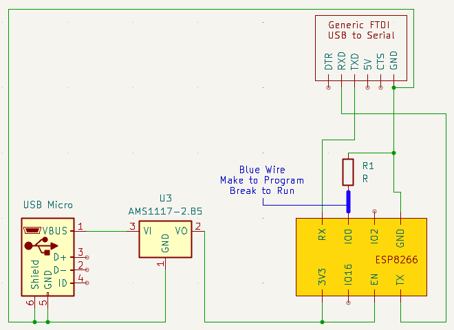
Most people will use an FTDI or similar based board to program their ESP8266s via serial connection. Beware that the ESP8266 needs 3V3 inputs, and reportedly cannot tolerate 5V on its pins.
Moreover, the ESP8266 needs an independent source of power, since the FTDI boards (if they even have a 3V3 power line) don’t provide enough power/current.
I built initially a programmer on a breadboard, and I used a few bits of kit to make this easier.
To put the ESP8266 into programming mode, the “0” IO pin must be held low (grounded). Many people incorporate a switch to make this easier. Initially I just manually connected and disconnected this pin to ground as needed.
I found it also necessary to hold the “chip enable” pin high (3V3) to be able to program the ESP8266.
Here is the schematic for how it was wired up.
To program the ESP8266 using the Arduino IDE, the procedure should be
pretty similar to programming an Arduino - we make sure the board is
selected (Generic ESP8266 Module), we make sure we are pointing to the
right “port” for the USB-to-serial board we are using (this will be
something like /dev/ttyUSB0, where the final number may
vary), and we hit “Upload”.
Of course, we need some code to compile and program the ESP8266 with. We want something which we can see working after it has been uploaded. I struggled for some reason to get a “blinky” program working (maybe the LEDs for my ESP8266 boards are on a weird pin?). Instead, I found the programs in File > Examples > ESP8266Wifi to be pretty useful, because any of those examples which connect to a WiFi AP is quite noisy over serial, which is easy to spy on with the Arduino IDE. For example, WiFiClient or WiFiClientBasic.
Of course, if the programming is generally going well, you’ll see this pretty quickly from the Arduino IDE output window.
For example, if we forgot to pull GPIO0 low at power-on, we see
esptool.py v3.0
Serial port /dev/ttyUSB0
Connecting........_____....._____....._____....._____....._____....._____....._____
A fatal esptool.py error occurred: Failed to connect to ESP8266: Timed out waiting for packet header
If everything is correctly configured instead, we see
esptool.py v3.0
Serial port /dev/ttyUSB0
Connecting....
Chip is ESP8266EX
Features: WiFi
Crystal is 26MHz
MAC: 5c:cf:7f:f2:56:8d
Uploading stub...
Running stub...
Stub running...
Configuring flash size...
Auto-detected Flash size: 1MB
Compressed 283312 bytes to 207820...
Writing at 0x00000000... (7 %)
Writing at 0x00004000... (15 %)

...etc...

Writing at 0x00030000... (100 %)
Wrote 283312 bytes (207820 compressed) at 0x00000000 in 18.3 seconds (effective 124.0 kbit/s)...
Hash of data verified.

Leaving...
Hard resetting via RTS pin...
On my basic breadboard, I then manually unplug and replug the 3V3 power to the board (and we should not forget to disconnected the resistor pulling GPIO0 low!).
We then open the serial monitor at 115200 baud, and if all has gone well, we see something like
Connecting to your-ssid
............
The exact output will vary depending upon which example sketch was chosen.
Broadly, we’ll need to do three or four things in our custom firmware
This is extensively covered in the ESP8266 examples in the Arduino IDE, so we don’t need to go over this in a lot of detail. Something like the following will do as a minimal starting point.
Throughout this code, we’ll leave in some Serial calls for debugging, but in a “real” build we would omit these.
#include <ESP8266WiFi.h>

const char* connect_to_ssid = "your-wifi-ssid-here";
const char* connect_to_password = "your-wifi-password-here";

void setup() {
  Serial.begin(115200);
  Serial.println("");
  Serial.print("Connecting to ");
  Serial.println(ssid);
  WiFi.mode(WIFI_STA);
  WiFi.begin(connect_to_ssid, connect_to_password);
  while (WiFi.status() != WL_CONNECTED) {
    delay(1000);
    Serial.print(".");
  }
  Serial.println("");
  Serial.println("WiFi connected");
  Serial.print("IP address: ");
  Serial.println(WiFi.localIP());
}

void loop() {
}
Ideally, we would have a way to “dynamically” set the WiFi ssid & password, like Tasmota, but that can come later.
Uploading and testing this, if all is well, we should see something like
Connecting to your-wifi-ssid-here
....
WiFi connected
IP address: 10.10.10.207
Of course, since loop() is empty, nothing else
happens.
It would be tiresome to have to provide a complete MQTT client
implementation, and luckily we won’t have to because someone has done
this for us. All the sources I found pointed to the PubSubClient
library. It seems there is a newer version of this than most sources
mentioned, which is called PubSubClient3. I found this under Sketch >
Include Library > Manage Libraries, then searched for PubSubClient,
and looked for PubSubClient3 (PubSubClient, v2.x, is still available),
then clicked Install. To include it, Sketch > Include Library >
Contributed Libraries > PubSubClient3. To the top of the file, this
adds #include <PubSubClient.h>.
Source code, documentation and examples are available here on the Github and an API documentation page.
There’s a great example available on the Github at the time of writing to follow.
We’ll obviously need the server’s address and port (1883 is standard for MQTT).
#include <ESP8266WiFi.h>
#include <PubSubClient.h>

// ...

const char* mqtt_host = "10.10.10.133";
const int mqtt_port = 1883;
We’ll create an MQTT client instance
// ...

const char* mqtt_host = "10.10.10.133";
const int mqtt_port = 1883;

WiFiClient espClient;
PubSubClient client(espClient);
To make a robust client, there’s quite a bit involved. So for now we won’t bother with reconnections etc…, we’ll just to try to connect once at startup.
Because the MQTT broker run by Home Assistant requires authentication, we’ll need to see how the connection is made in the MQTT auth example.
The connect call is
client.connect("arduinoClient", "testuser", "testpass"). So
in addition to the host we’ll need the username and password. For me,
this will be the one set up for Tasmota, but I think it will/should work
with any Home Assistant user.
// ...

const char* mqtt_host = "10.10.10.133";
const int mqtt_port = 1883;
const char* mqtt_user = "your-home-assistant-username-here";
const char* mqtt_password = "your-home-assistant-password-here";
The first argument to the connect call is a client id, which I believe should ideally be unique per MQTT broker. Hence we can set up a client id based on e.g. a UUID.
// ...

const char* mqtt_host = "10.10.10.133";
const int mqtt_port = 1883;
const char* mqtt_client_id = "956ede62da5a488ab7926712e999cb47";
const char* mqtt_user = "your-home-assistant-username-here";
const char* mqtt_password = "your-home-assistant-password-here";
Then on setup we point to our MQTT broker
void setup() {
  // ...
  Serial.print("IP address: ");
  Serial.println(WiFi.localIP());

  client.setServer(mqtt_host, mqtt_port);
}
Try to connect to it, recording the outcome
void setup() {
  // ...
  client.setServer(mqtt_host, mqtt_port);
  bool connected = client.connect(mqtt_client_id, mqtt_user, mqtt_password);
}
And “log” the outcome on serial
void setup() {
  // ...
  client.setServer(mqtt_host, mqtt_port);
  bool connected = client.connect(mqtt_client_id, mqtt_user, mqtt_password);
  Serial.print("MQTT connected? ");
  Serial.print(connected);
  Serial.print(" Code ");
  Serial.println(client.state());
}
On my first attempt uploading and running this, I saw
Connecting to ...
....
WiFi connected
IP address: 10.10.10.207
MQTT connected? 0 Code -2
I had to check the API docs to find the meaning of code -2
Returns
    -4 : MQTT_CONNECTION_TIMEOUT - the server didn't respond within the keepalive time
    -3 : MQTT_CONNECTION_LOST - the network connection was broken
    -2 : MQTT_CONNECT_FAILED - the network connection failed
    -1 : MQTT_DISCONNECTED - the client is disconnected cleanly
    0 : MQTT_CONNECTED - the client is connected
    1 : MQTT_CONNECT_BAD_PROTOCOL - the server doesn't support the requested version of MQTT
    2 : MQTT_CONNECT_BAD_CLIENT_ID - the server rejected the client identifier
    3 : MQTT_CONNECT_UNAVAILABLE - the server was unable to accept the connection
    4 : MQTT_CONNECT_BAD_CREDENTIALS - the username/password were rejected
    5 : MQTT_CONNECT_UNAUTHORIZED - the client was not authorized to connect
This was only kind of helpful. I knew the WiFi connection was
successful, so I assumed something was going wrong “downstream” of that.
It turned out that I had used the wrong IP address, not the IP address
of Home Assistant on my network. D’oh! With the IP address
(mqtt_host) fixed… the same outcome.
I had a small hunch (not really based on any evidence) that the WiFi
connection wasn’t quite “ready” for some reason and I was trying to
connect to the MQTT broker too quickly. So I tried inserting a short
delay delay(250) before attempting the MQTT connection.
...
MQTT connected? 1 Code 0
Success - 1 for boolean true and code
0 means MQTT_CONNECTED!
In the connection code of the example file, there is also a function
call to subscribe to a certain topic, which we’ll replicate in our
program. We’ll use the Tasmota command topic from the start of these
notes, i.e. cmnd/tasmota_DEVICE_SHORT_ID/Power1, to spy on
commands sent to the Tasmota smart plug.
void setup() {
  // ...
  Serial.print(" Code ");
  Serial.println(client.state());
  client.subscribe("cmnd/tasmota_DEVICE_SHORT_ID/Power1");
}
Then we’ll need a “callback” to actually do something when any messages received on that topic. The form of the callback is taken from the example code
void callback(char* topic, byte* payload, unsigned int length) {
}
We see that we’ll receive the topic (I guess in case we are subscribed to multiple topics), the payload as a byte sequence and the length of the payload (number of bytes we should read).
To start with, let’s just print the topic and the payload, assuming the payload will be ASCII-string-y.
void callback(char* topic, byte* payload, unsigned int length) {
  Serial.print("Topic ");
  Serial.print(topic);
  Serial.print(" received '");
  if (length < 255) {
    for (uint8_t i=0; i<length; i++) {
      Serial.print((char) payload[i]);
    }
  }
  Serial.println("'");
}
The payload bytes are cast as (char)s, else I think they will be printed as numbers (e.g. ‘65’ instead of ‘A’).
Finally, we need to tell the client to actually use this callback, again lifted directly from the example code
void setup() {
  // ...
  Serial.print(" Code ");
  Serial.println(client.state());
  client.setCallback(callback);
  client.subscribe("cmnd/tasmota_DEVICE_SHORT_ID/Power1");
}
We configure the callback before the subscription to avoid a scenario where we are receiving messages but are not handling them with the callback, however unlikely that is to happen in practice.
At first this did not work. Nothing was printed on serial when sending messages on the Tasmota topics. I noticed that subscribe returns a boolean indicating success, so first we can print this and ensure it’s true
void setup() {
  // ...
  client.setCallback(callback);
  client.subscribe("cmnd/tasmota_DEVICE_SHORT_ID/Power1");
  Serial.print("MQTT subscribed? ");
  Serial.println(subscribed);
}
and subscribing was indeed successful
...
MQTT connected? 1 Code 0
MQTT subscribed? 1
Checking again the example, I noticed that I had forgotten to run the
client loop! client.loop() in the loop()
function in the example code. We need to explicitly tell the client when
it can process messages, because obviously we’re not working in an
environment where doing this asynchronously in software is trivial. When
we add this call to our loop()
void loop() {
  client.loop();
}
Finally, we are capturing some MQTT messages! I see this in the serial monitor when toggling the smart plug on and off.
MQTT connected? 1 Code 0
MQTT subscribed? 1
Topic cmnd/tasmota_DEVICE_SHORT_ID/Power1 received 'OFF'
Topic cmnd/tasmota_DEVICE_SHORT_ID/Power1 received 'ON'The example also illustrates how to publish to a topic. This is the last piece of the MQTT puzzle that we need - subscribing to a topic will allow us to control a device remotely (e.g. switching it on and off in Home Assistant) and publishing to a topic will allow us to report that the device has taken some action (e.g. has switched on or off) back to a system like Home Assistant.
As is pretty common when passing messages between different bits of code in embedded device C, the mechanism to tell the client what to publish involves a buffer. So we’ll need to create a buffer first
// ...

WiFiClient espClient;
PubSubClient client(espClient);

const uint16_t maximum_message_length = 20;
char outgoing_message[maximum_message_length];
With this we can send messages up to 19 characters in length. We’ll see why it’s 19 and not 20 shortly.
Initially, let’s just send a constant message to a topic that won’t mean anything to Home Assistant.
const char* fixed_message = "TEST";
const uint8_t message_size = 4;

void loop() {
  client.loop();
  // ...
To send the message, we copy it into the buffer
outgoing_message and we terminate it with a \0
character, to make it a “C string”
void loop() {
  client.loop();

  for (uint8_t i=0; i<message_size; i++) {
    outgoing_message[i] = fixed_message[i];
  }
  outgoing_message[message_size] = '\0';
}
That’s why the maximum message size is 19 characters with a buffer size of 20 - we must always add the null terminator.
Now we can call publish on the client.
We’ll also add a delay so we are not spamming the message
queue with these messages every few-tens of milliseconds.
void loop() {
  client.loop();

  for (uint8_t i=0; i<message_size; i++) {
    outgoing_message[i] = fixed_message[i];
  }
  outgoing_message[message_size] = '\0';
  client.publish("state/device/test", outgoing_message);

  delay(1000);
}
We had best not forget some Serial logging, so we have observability into what the device is doing!
void loop() {
  client.loop();

  for (uint8_t i=0; i<message_size; i++) {
    outgoing_message[i] = fixed_message[i];
  }
  outgoing_message[message_size] = '\0';
  Serial.print("About to send message: ");
  Serial.println(outgoing_message);
  bool published = client.publish("state/device/test", outgoing_message);
  Serial.print("Successfully published? ");
  Serial.println(published);

  delay(1000);
}
First we’ll check everything looks reasonable in the serial monitor
Connecting to your-wifi-ssid
....
WiFi connected
IP address: 10.10.10.207
MQTT connected? 1 Code 0
MQTT subscribed? 1
About to send message: TEST
Successfully published? 1
About to send message: TEST
Successfully published? 1
About to send message: TEST
Successfully published? 1
...
Everything certainly looks promising!
To check that the messages are really being sent with the expected
content and on the expected topic, we’ll need to monitor with
mqttx
mqttx sub -t '#' -h homeassistant.lan -p 1883 -u $MQTT_USER -P $MQTT_PASSWORDThis is the lazy way, subscribing to all topics, so we’ll probably see some other messages interleaved with the ones we are publishing
✔ Connected
✔ Subscribed to #
... unrelated "retained" messages

topic: state/device/test, qos: 0
TEST

topic: state/device/test, qos: 0
TEST

topic: state/device/test, qos: 0
TEST

...
This looks great - we’re really publishing the messages we expect to the topic we expect on the MQTT broker.
Obviously, instead of publishing always a fixed message, it’s much more likely that we’ll want to publish a message which changes based on some state. This could be the state of the device (on/off, e.g.) or it could be e.g. the state of the outside world if we’re integrated with a sensor (a temperature or a light intensity, e.g.).
To investigate this, let’s do the most straightforward thing we can in the context of the current code, storing the incoming message and echoing it back out.
We’ll create a new buffer to store that message
// ...
const uint16_t maximum_outgoing_message_length = 20;
char outgoing_message[maximum_outgoing_message_length];

const uint16_t maximum_incoming_message_length = 20;
char incoming_message[maximum_incoming_message_length];
Then when we receive a message, we’ll capture it in the buffer. First, we need to make sure the message we capture is at most as long as the maximum message length we can store (19 characters)
void callback(char* topic, byte* payload, unsigned int length) {
  unsigned int truncated_length = maximum_incoming_message_length - 1;
  if (length < truncated_length) {
    truncated_length = length;
  }
}
Now copy this across into the buffer with a null terminator
void callback(char* topic, byte* payload, unsigned int length) {
  unsigned int truncated_length = maximum_incoming_message_length - 1;
  if (length < truncated_length) {
    truncated_length = length;
  }
  for (uint8_t i=0; i<truncated_length; i++) {
    incoming_message[i] = (char)payload[i];
  }
  incoming_message[truncated_length] = '\0';
}
We’ll also store the length, so we don’t later have to work it out by walking through the string looking for ‘\0’. This variable is marked volatile since it can (in principle) change at any time from any execution context (I’m not sure how important this is in practise in the ESP8266). Note that we’ve stored the length of the message without the null terminator.
volatile uint8_t stored_message_length = 0;

void callback(char* topic, byte* payload, unsigned int length) {
  unsigned int truncated_length = maximum_incoming_message_length - 1;
  if (length < truncated_length) {
    truncated_length = length;
  }
  for (uint8_t i=0; i<truncated_length; i++) {
    incoming_message[i] = (char)payload[i];
  }
  incoming_message[truncated_length] = '\0';
  stored_message_length = truncated_length;
}
Finally, let’s adjust our debug Serial logs for how the
message is now being stored
void callback(char* topic, byte* payload, unsigned int length) {
  unsigned int truncated_length = maximum_incoming_message_length - 1;
  if (length < truncated_length) {
    truncated_length = length;
  }
  for (uint8_t i=0; i<truncated_length; i++) {
    incoming_message[i] = (char)payload[i];
  }
  incoming_message[truncated_length] = '\0';
  stored_message_length = truncated_length;
  Serial.print("Topic ");
  Serial.print(topic);
  Serial.print(" received '");
  Serial.print(incoming_message);
  Serial.print("' length ");
  Serial.print(stored_message_length);
  Serial.println("");
}
We can quickly test that this is working before making changes to publishing - in the serial monitor we see (interleaved with the publishing messages)
MQTT connected? 1 Code 0
MQTT subscribed? 1
...
Topic cmnd/tasmota_DEVICE_SHORT_ID/Power1 received 'ON' length 2
...
Topic cmnd/tasmota_DEVICE_SHORT_ID/Power1 received 'OFF' length 3
This all looks in order. Before moving on to publishing, instead of
using the fixed message, we’ll use the message in this buffer. We first
delete the fixed_message and message_size
constants, then
// ...
}

void loop() {
  client.loop();

  for (uint8_t i=0; i<stored_message_size; i++) {
    outgoing_message[i] = incoming_message[i];
  }
  outgoing_message[message_size] = '\0';
  Serial.print("About to send message: ");
  Serial.println(outgoing_message);
  bool published = client.publish("state/device/test", outgoing_message);
  Serial.print("Successfully published? ");
  Serial.println(published);

  delay(1000);
}
Lastly, we’ll only start publishing when there is a message to publish
void loop() {
  client.loop();

  if (stored_message_length > 0) {
    for (uint8_t i=0; i<stored_message_length; i++) {
      outgoing_message[i] = incoming_message[i];
    }
    outgoing_message[stored_message_length] = '\0';
    Serial.print("About to send message: ");
    Serial.println(outgoing_message);
    bool published = client.publish("state/device/test", outgoing_message);
    Serial.print("Successfully published? ");
    Serial.println(published);
  }

  delay(1000);
}
Now we see output
...
MQTT connected? 1 Code 0
MQTT subscribed? 1
... sits here until the first time we toggle the switch
Topic cmnd/tasmota_DEVICE_SHORT_ID/Power1 received 'ON' length 2
About to send message: ON
Successfully published? 1
About to send message: ON
Successfully published? 1
... repeats until we toggle the switch
Topic cmnd/tasmota_DEVICE_SHORT_ID/Power1 received 'OFF' length 3
About to send message: OFF
Successfully published? 1
About to send message: OFF
Successfully published? 1
... repeats until we toggle the switch
Exactly what we expect! With one tiny tweak though we will only
publish the message once when it is “new” to the device. Resetting the
stored_message_length to zero here means the
if will not run, and changes slightly the meaning of the
stored_message_length variable - when zero then no message
to send, else length of the message. Strictly speaking we ignore here
whether the message was successfully published or not, which means
messages could be dropped - maybe that’s fine for our real application,
maybe it’s not - which is certainly good enough for testing.
void loop() {
  client.loop();

  if (stored_message_length > 0) {
    for (uint8_t i=0; i<stored_message_length; i++) {
      outgoing_message[i] = incoming_message[i];
    }
    outgoing_message[stored_message_length] = '\0';
    Serial.print("About to send message: ");
    Serial.println(outgoing_message);
    bool published = client.publish("state/device/test", outgoing_message);
    Serial.print("Successfully published? ");
    Serial.println(published);
    stored_message_length = 0;
  }

  delay(1000);
}
Now in the output we see
...
MQTT connected? 1 Code 0
MQTT subscribed? 1
Topic cmnd/tasmota_DEVICE_SHORT_ID/Power1 received 'ON' length 2
About to send message: ON
Successfully published? 1
Topic cmnd/tasmota_DEVICE_SHORT_ID/Power1 received 'OFF' length 3
About to send message: OFF
Successfully published? 1
The published message log lines do not repeat however long we wait,
and we can verify with mqttx that the messages are only
sent once.
When we run this code in its current state, we will find that quite often the MQTT connection fails initially. To try again to connect it is necessary to restart the whole device. Obviously this is not what we would want if we were controlling something real with an ESP8266 - turn it off and on again each time it loses connection.
The example code actually suggests, and we’ll now implement in our code, a reconnection strategy. Let’s move the code which connects to the MQTT broker and sets up the subscription to its own function, and call that from the main loop instead.
void ensure_mqtt_connected() {
  client.setServer(mqtt_host, mqtt_port);
  bool connected = client.connect(mqtt_client_id, mqtt_user, mqtt_password);
  Serial.print("MQTT connected? ");
  Serial.print(connected);
  Serial.print(" Code ");
  Serial.println(client.state());
  client.setCallback(callback);
  bool subscribed = client.subscribe("cmnd/tasmota_DEVICE_SHORT_ID/Power1");
  Serial.print("MQTT subscribed? ");
  Serial.println(subscribed);
}

void setup() {
  Serial.begin(115200);
  Serial.println("");
  Serial.print("Connecting to ");
  Serial.println(connect_to_ssid);
  WiFi.mode(WIFI_STA);
  WiFi.begin(connect_to_ssid, connect_to_password);
  while (WiFi.status() != WL_CONNECTED) {
    delay(1000);
    Serial.print(".");
  }
  Serial.println("");
  Serial.println("WiFi connected");
  Serial.print("IP address: ");
  Serial.println(WiFi.localIP());
}

void loop() {
  ensure_mqtt_connected();
  client.loop();

  //...
Of course, the code will now try to reconnect on every loop regardless of whether we already have a connection established. To resolve this we should check if the client is connected, and only then try to reconnect. Then, instead of doing this just once in ensure_mqtt_connected, checking repeatedly and repeating the connection until we have a connection will make the function live up to its name.
void ensure_mqtt_connected() {
  while (!client.connected()) {
    delay(250);
    Serial.print("Reconnecting to MQTT at ");
    Serial.print(mqtt_host);
    Serial.print(":");
    Serial.println(mqtt_port);
    client.setServer(mqtt_host, mqtt_port);
    bool connected = client.connect(mqtt_client_id, mqtt_user, mqtt_password);
    Serial.print("MQTT connected? ");
    Serial.print(connected);
    Serial.print(" Code ");
    Serial.println(client.state());
    client.setCallback(callback);
    bool subscribed = client.subscribe("cmnd/tasmota_DEVICE_SHORT_ID/Power1");
    Serial.print("MQTT subscribed? ");
    Serial.println(subscribed);
  }
}
A delay has been added to avoid hammering the broker too hard, and some additional log lines for better observability.
Re-running we’ll typically get some output when it works the first time like
Connecting to your-wifi-ssid
....
WiFi connected
IP address: 10.10.10.207
Reconnecting to MQTT at homeassistant.lan:1883
MQTT connected? 1 Code 0
MQTT subscribed? 1
or when it doesn’t work the first time
Connecting to your-wifi-ssid
....
WiFi connected
IP address: 10.10.10.207
Reconnecting to MQTT at homeassistant.lan:1883
MQTT connected? 0 Code -2
MQTT subscribed? 0
Reconnecting to MQTT at homeassistant.lan:1883
MQTT connected? 1 Code 0
MQTT subscribed? 1With this, we have the basic foundation we need for building an ESP8266 based device that interacts with MQTT and thence Home Assistant. Everything else we do around this - toggling GPIO pins, reading sensor values, etc… - is decided by what our device does, which (together with Home Assistant’s specifications) determine what messages we will need to send on which topics and at what times.